Wohner products connect head

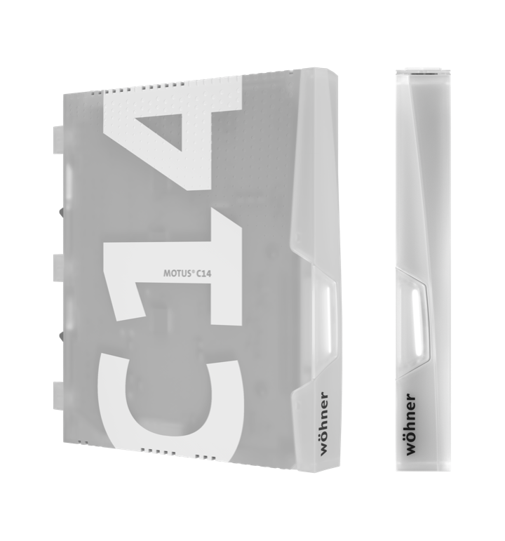
Motus®C14
Connect

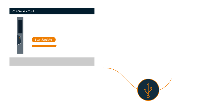
The Connect version has an integrated USB interface. This is used for programming via ServiceTool.

The communication interface enables connection to intelligent sensors and actuators in an automation system or bus systems through a gateway.

Motus®C14 Connect

signalling

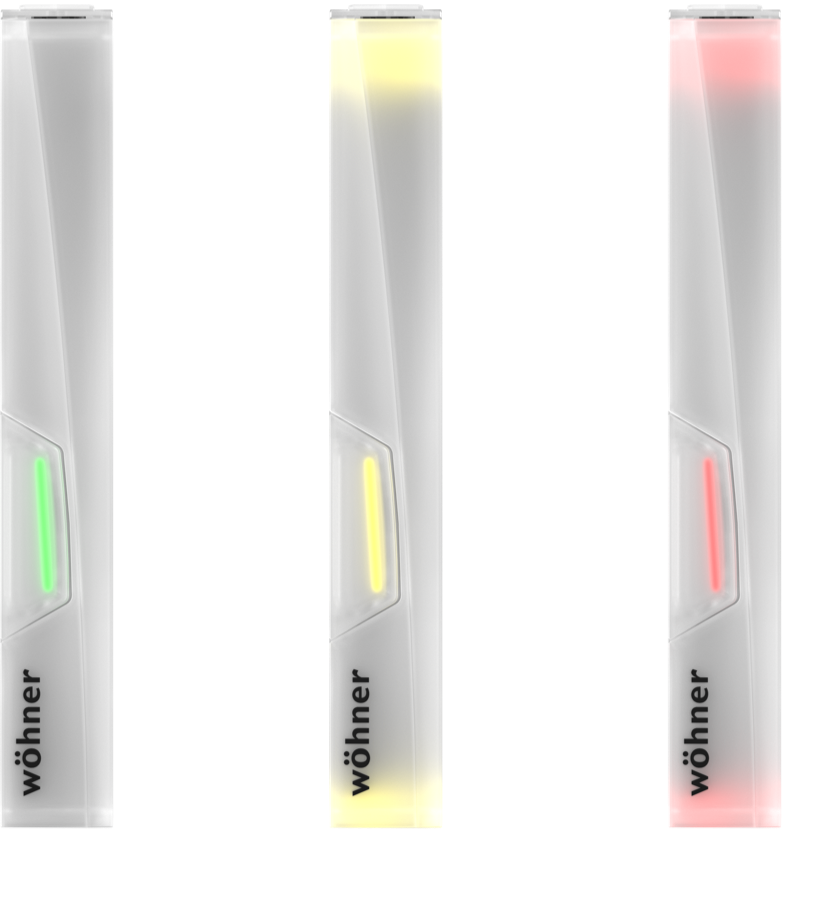
The LEDs integrated on the device light up in yellow or red, depending on the functional status of the device. Warnings are displayed in yellow and faults in red.

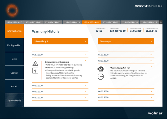
The fault messages can be retrieved via the ServiceTool, transmitted via the communication interface or evaluated via analogue relay outputs.

Wohner products connect signal en

Motus®C14 Connect

parametrisation/control

  • current setting
  • characteristic setting for all motor classes
  • 8 adjustable tripping classes
    (2E, 3E, 5, 10, 10A, 20, 30, 40E)
  • threshold value settings for current and voltage
  • fixed threshold values for temperature
  • variable fan speed for optimal temperature management
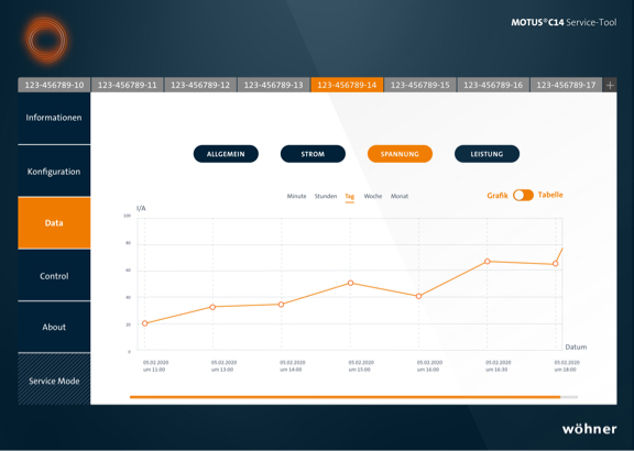
  • access to internal real-time data: current, voltage, power
  • direct start
  • reversing start
  • soft start optional
  • switching resistive loads
  • galvanic break
Wohner products connect parameterization
  • Parametrization web
    parameterisation and control via web application
  • Parametrization usb
    parameterisation via USB interface on the device

Motus®C14 Connect

ServiceTool

Commissioning – Parameterisation – Data logging

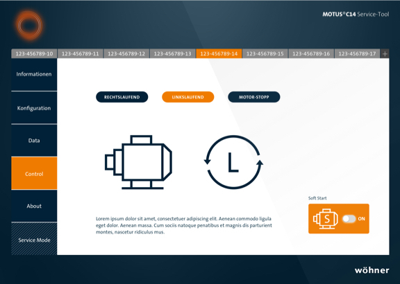
The ServiceTool of Wöhner provides the following functionalities:

  • commissioning and setting parameters
  • manual control of the drive
  • import and export of data

System – Software

  • connection of the devices via a USB-C interface
  • for safety reasons software updates of the MOTUS®C14 can only be done via the USB-C interface
  • download available for Windows 10 or macOS
Service tool schema

Motus®C14 Connect

connections

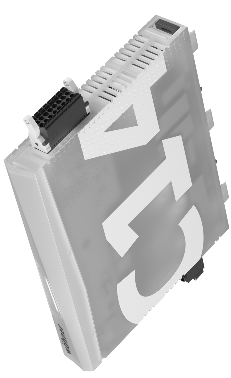
All connections of the MOTUS®C14 are pluggable and thus enable quick wiring of the devices.

  • Top view
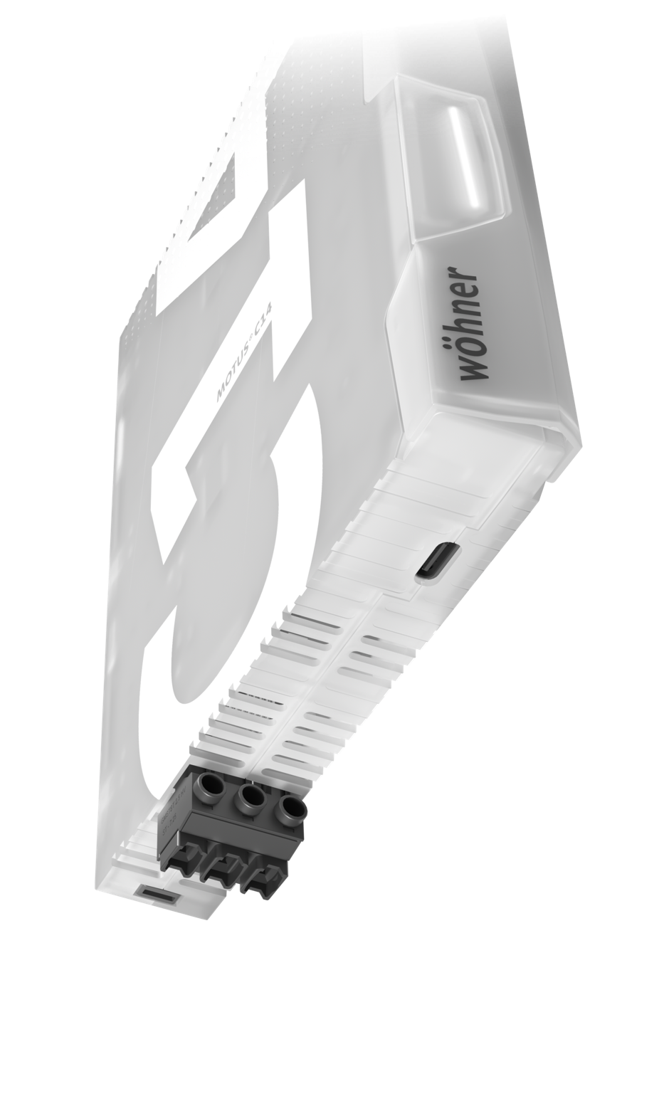
  • Bottom view
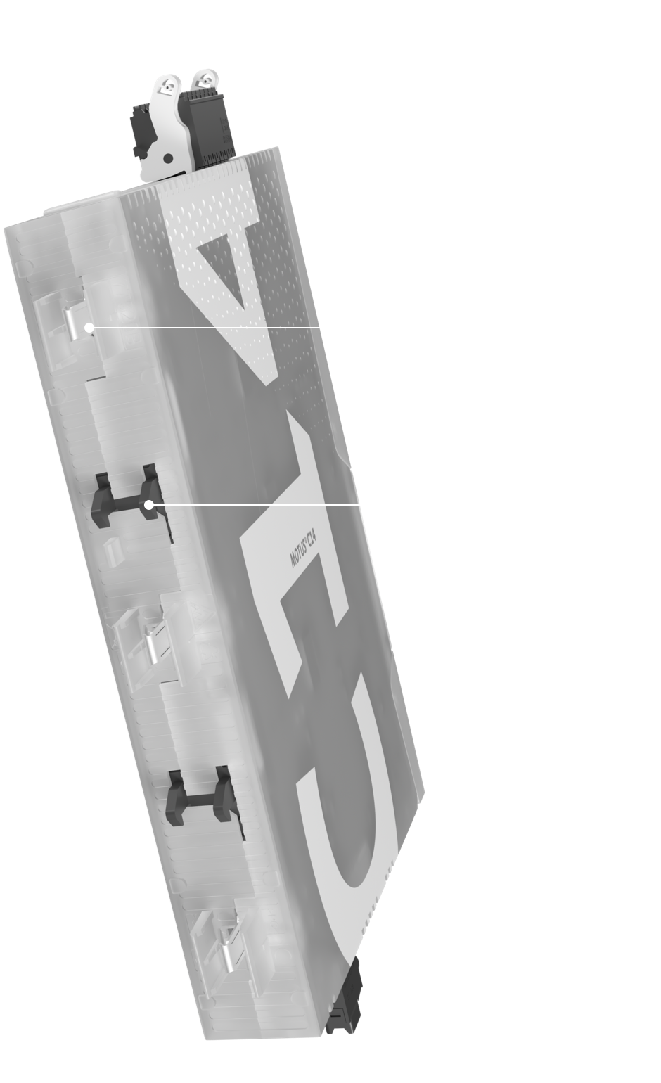
  • Back view
  • MOTUS®C14 Connect control plug

    The control plug is located on the upper section of the MOTUS®C14. It can be used either for conventional or
    IO-Link wiring.

    With IO-Link wiring, the connection is made via 3 wires: supply voltage 24 V DC (+), GND and C/Q data.

  • Conect Plus Stecker connect 02 bottom en

    The lower section of the MOTUS®C14 is used to wire the T1, T2 and T3 load plug. This has screw clamp connection.

    The USB interface is also located on this side. This interface enables via the ServiceTool the parameterisation and the data retrieval of the device.

  • Conect Plus Stecker connect 03 side en

    The MOTUS®C14 uses CrossLink®Technology and can be plugged directly onto the CrossBoard®. With an adapter, the device can be mounted on the systems 30Compact and 60Classic or in the system Panel on the DIN mounting rail. With all types, the contacts of the CrossLink® adapter or the CrossBoard® remain touch-safe while removing the electronic unit.

    The mechanical and electrical connection (up to 500 V) is done without using tools when the device is snapped onto the CrossLink® interface during installation. The integrated contact protection prevents the contacts from being damaged during transport, mounting and dismounting.
  • MOTUS®C14 Connect control plug
  • Conect Plus Stecker connect 02 bottom en
  • Conect Plus Stecker connect 03 side en

Motus®C14 Connect

technical details

The MOTUS®C14 switches faster than circuit breakers and faster than fuses in case of a fault.

1010
microseconds
C14-Technology
extremely fast switch-off time in case of fault

20002000
microseconds
Fuse-Link
switch-off time in case of fault
50005000
microseconds
Circuit breaker
switch-off time in case of fault
rated operating voltage 130 - 500 V (IEC)
130 - 480 V (UL)
rated operating current
for motors
2.6 A / 1.1 kW
6.6 A / 3.0 kW
rated operating current
for resistive loads
2.6 A / 1.8 kW
6.6 A / 4.5 kW
short-circuit resistance 100 kA, coordination type 2
control voltage 24 V DC
electrical switching cycles > 30 million
connection plugs control circuit: 0.2 - 1.5 mm² (solid, flexible) / AWG 24 - 16
load circuit: 0.2 - 2.5 mm² (solid, flexible) / AWG 24 - 14
dimensions
(w x h x d)
CrossBoard®: 22.5 x 160 x 130 mm
30Compact: 22.5 x 160 x 130 mm + 14 mm adapter
60Classic: 22.5 x 200 x 130 mm + 14 mm adapter
approval IEC IEC / EN 60947-4-2 / -3
approvel UL UL listed (C-UL-US)
article overview MOTUS®C14 Connect Plus - CrossBoard®
36246: electronic unit 0.1 - 2.6 A / switch for resistive loads 0.1 - 2.6 A
36250: electronic unit 0.1 - 6.6 A / switch for resistive loads 0.1 - 6.6 A

MOTUS®C14 Connect Plus - 30Compact
36244: reversing starter 0.1 - 2.6 A / switch for resistive loads 0.1 - 2.6 A
36248: reversing starter 0.1 - 6.6 A / switch for resistive loads 0.1 - 6.6 A

MOTUS®C14 Connect Plus - 60Classic
36245: reversing starter 0.1 - 2.6 A / switch for resistive loads 0.1 - 2.6 A
36249: reversing starter 0.1 - 6.6 A / switch for resistive loads 0.1 - 6.6 A

MOTUS®C14 Connect Plus - Panel
36243: reversing starter 0.1 - 2.6 A / switch for resistive loads 0.1 - 2.6 A
36247: reversing starter 0.1 - 6.6 A / switch for resistive loads 0.1 - 6.6 A

MOTUS®C14 CONNECT

MAXIMUM INRUSH CURRENTS

Bar chart shows the maximum inrush currents in cold state for a single start

Motus c14 connect anlaufstroeme en

MOTUS®C14 CONNECT

CURRENT CHARACTERISTICS

Permissible repeatable overcurrent factor to rated operating current (AC-53a)

Motus c14 connect stromkennlinien en